A: A standard "null-modem serial
cable" (optionally attached to the PC via a USB
serial interface), or a Bluetooth
serial adapter.
The null-modem cable needs to be wired for "full
handshaking" (not "loopback handshaking" or
"partial handshaking"). These cables are architecture-neutral, i.e. they are
the same for PC, Amiga and other systems.
The Amiga generally has
a 25-pin serial port connector (on the back), whereas PCs
use both 9-pin and 25-pin connectors. If the
PC does not have a serial port, you can use
an inexpensive USB serial adapter.
On both Amiga and PC systems, be careful
not to confuse the serial port (male
connector) with the parallel port (female
connector). Also, the Amiga has two 9-pin
mouse/joystick connectors on the side, which
are not serial ports.
Belkin, for example,
lists a high-quality, universal (9-pin and 25-pin connectors on both
sides, i.e. a total of four connectors) null-modem cable as model number
F3X171-10 ("Pro Series File Transfer - PC to PC Cable -
Serial").
QVS offers a similar "Universal Serial File Transfer Cable"
as part number CC327-10, which we also tested successfully. In our
experience prices for such "universal" null-modem cables (i.e.
those with four connectors) vary between about $10 and $30, even for the
same product sold at different locations. Regular null-modem cables tend
to sell in the $5-$7 range.
We did receive a few reports about commercial cables that were not wired as
needed, and in many cases this was due to the cables not being meant for "full
handshaking". Please refer to the section on
null-modem cables
in the Amiga Explorer documentation for detailed and complete information on this
topic, including non-standard Amiga serial ports.
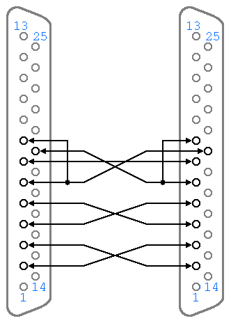
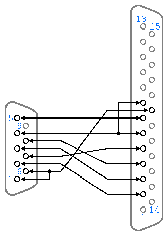
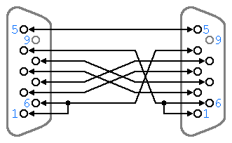
The following drawings show three
null-modem wiring configurations (choose the
one that applies based on your combination
of PC/Amiga connectors). The numbers refer
to the external side of the male connector
(or the internal side of the female
connector). Female connectors usually have
the numbers printed in matching (mirrored)
order on the outside.

DB-25 connectors on both ends

DB-9 connector on one end,
DB-25 on the other end

DB-9 connectors on both ends
If you purchased a null-modem cable, and it does not work, please compare it with the
schematics in the Amiga Explorer documentation. No parts in this
wiring are "redundant".
If you need to use a "gender
changer" to attach a null-modem serial cable to the serial
port on the back of your computer, it probably means that the cable is not a
null-modem serial cable. Null-modem cables should always have female
connectors on both sides, and all computers should have male
connectors for their serial ports. (A known exception to this are
some early Amiga 1000 models. A small number of these had female
serial port connectors. If you are in doubt check the indications
appearing near the connectors.)
The serial port was used for modems,
and may have a telephone symbol next to it. The parallel port
(which is not used with Amiga Explorer) is
normally used for printers, and may have a
printer symbol next to it.
Warning: the 25-pin female connector on
the back of many computers is a parallel port (not a serial port).
While a null-modem serial cable will not attach to it (as it also uses female connectors), certain other combinations of cables and gender
changers can in theory be used to try to connect a parallel port
on one computer with the serial port of another computer. This
should never be attempted, as it may damage one or both
computers.
For some applications, including
terminal software when no hardware handshaking is used, very
simple null-modem cables with three wires are sufficient to
exchange data (although not in the most reliable and efficient
way). This is accomplished by connecting GND (system ground) on
both sides, and cross-connecting TxD (transmit data) with RxD
(receive data). Amiga Explorer, like many other programs,
additionally uses RTS and CTS for hardware handshaking, and DTR
and DSR for each side to inform the other side whether it is ready
to process data or not. This ensures, for example, that if there
is an overflow in the serial port's input data buffer, the other
side stops transmitting, and waits until the buffer is ready to
receive more data.
Amiga Explorer requires a
complete null-modem cable, with 7 wires. High quality commercial
cables follow this specification, but lower quality and
"do-it-yourself" cables sometimes differ. If the wires
are not connected properly, Amiga Explorer will not work. In some
cases, including proper connections but poor quality or too long
cables, Amiga Explorer may transfer short files, but it will fail
with longer files (in one or both directions). In other cases, the
software will not work at all. The Amiga serial port also uses
non-standard signals (see the Amiga Forever documentation), which
may damage the equipment on the other side. This cannot happen
with a properly wired null-modem cable.
The pins for all DB-9/25
connectors are numbered in such a way that each pin number always
corresponds to the same pin number on the other side. For example,
pin 1 always connects to pin 1, and is always numbered
"1" in all of the above illustrations and tables,
regardless of whether it is "male" or
"female", or viewed from "inside" or
"outside". All pins along this electrical path are
numbered "1".
It is very important that the
pins which on the different Amiga models supply power (9, 10, 14,
21, 23) be not connected to any active pins on the PC. Also, the
two different grounds (shield ground and system ground) should not
be connected with each other.
Cables longer than 20 meters (65 feet) should be used with
additional care. Special low capacitance cables are better suited for longer
distances. Shielded cables and connectors should be used if the cables are
close to electrical equipment, which could add noise to the signals. The cable
shielding should be connected to the shielding of one of the two sockets. Lower
baud rates may help reduce transmission problems over long and/or noisy lines. The use of additional
connectors, adapters and extension wires should be kept to a
minimum, as each additional component tends to reduce the quality
of the connection.
Related Links


